
- #Siemens step 7 install#
- #Siemens step 7 manual#
- #Siemens step 7 software#
- #Siemens step 7 series#
- #Siemens step 7 windows#
You can make use of these reference data to make debugging and modifying your user program easier (see also Overview of the Available Reference Data). S7 only: generate and evaluate reference data Using one of the available programming languages create a program linked to a module or independent of a module and store it as blocks, source files, or charts (see also Basic Procedure for Creating Logic Blocks and Basic Information on Programming in STL Source Files).


You can define local or shared symbols, which have more descriptive names, in a symbol table to use instead of absolute addresses in your user program (see also Creating a Symbol Table). For this, you will need to create the subnets required for your automation networks, set the subnet properties, and set the network connection properties and any communication connections required for the networked stations (see also Procedure for Configuring a Subnet). The basis for communication is a pre-configured network. Ĭonfigure networks and communication connections The properties of the modules can also be assigned using parameters (see also Basic Procedure for Configuring Hardware). When you configure the hardware you specify in a configuration table which modules you want to use for your automation solution and which addresses are to be used to access the modules from the user program. When you configure the station you specify the programmable controller you want to use for example, SIMATIC 300, SIMATIC 400, SIMATIC S5 (see also Inserting Stations). After you have created a project, all other tasks are executed in this project (see also Project Structure).
#Siemens step 7 windows#
You start STEP 7 from the Windows user interface (see also Starting STEP 7).Ī project is like a folder in which all data are stored in a hierarchical structure and are available to you at any time. Turn the tasks described in the draft of your controller design into a program structure using the blocks available in STEP 7 (see also Blocks in the User Program).
#Siemens step 7 install#
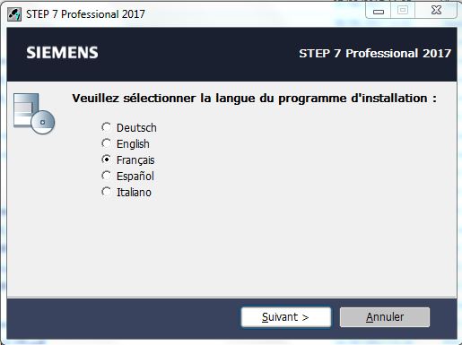
The first time you use STEP 7, install it and transfer the license keys from diskette to the hard disk (see also Installing STEP 7 and Authorization).īefore you work with STEP 7, plan your automation solution from dividing the process into individual tasks to creating a configuration diagram (see also Basic Procedure for Planning an Automation Project). This is recommended for service and maintenance work, for example, to integrate programmed blocks into in an existing project.īrief Description of the Individual Steps You can, however, program the blocks first without configuring the hardware. You can configure the hardware first and then program the blocks.
#Siemens step 7 manual#
It refers you to the relevant chapter thus giving you the opportunity of moving through the manual to find task-related information.Īs shown in the figure above, you have two alternative procedures: The following figure shows the tasks that need to be performed for most projects and assigns them to a basic procedure.
#Siemens step 7 series#
When you create an automation solution with STEP 7, there are a series of basic tasks. STEP 7 is the subject of this documentation, STEP 7 Micro is described in the "STEP 7 Micro/DOS" documentation. Opportunity of assigning parameters to function modules and communications processorsĮvent-driven data transfer using communication function blocks

#Siemens step 7 software#
STEP 7 for applications on SIMATIC S7-300/S7-400, SIMATIC M7-300/M7-400, and SIMATIC C7 with a wider range of functions:Ĭan be extended as an option by the software products in the SIMATIC Industry Software (see also Extended Uses of the STEP 7 Standard Package) STEP 7 Micro/DOS and STEP 7 Micro/Win for simpler stand-alone applications on the SIMATIC S7-200. There are the following versions of the STEP 7 Standard package: It is part of the SIMATIC industry software. Learn more about DMC's PLC Programming services and contact us to get started on your next PLC Programming project.STEP 7 is the standard software package used for configuring and programming SIMATIC programmable logic controllers.


 0 kommentar(er)
